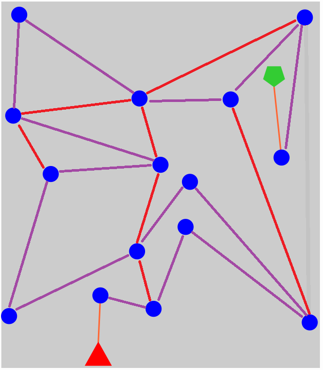
My Solution (by hand):
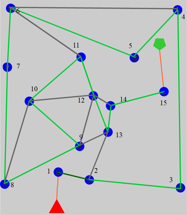
My Findings & Strategies:
The signal leaves the node at the exit that is "s mod n" turns clockwise from where it entered; where s is the signal strength, n is the number of connections to the node and "mod" is the modulus (remainder of the division).
The signal may not travel back the way it came from, since it would visit a node it already visited. Hence a node must have at least two connections, except for the start (triangle) and end (pentagram) nodes.
Nodes having and odd signal strength are simpler. Since "s mod 2" is always 1 for an odd s, which means the signal leaves the other path, if there is only one other path! However, this only works as long as there are two connections!
Nodes with even signal strength must have a connection count which the signal strength can't be divided by. Else "s mod n" would be 0, which (according to 1.) means: The signal travels back where it came from.
The highest possible connection count without crossing the existing connections or touching other nodes is 13 (tried by hand). These are the maximum number of connections for each node: A: 7, B: 8, C: 8, D: 10, E: 11, F: 11, G: 13, H: 13, I: 9, J: 10, K: 9, L: 13, M: 9, N: 10, O: 7. However, connections between other nodes might reduce this number, as crossing connections are not allowed.
There are 15 nodes to visit (with strength 1,2,3, ..., 15). Their only possible connection counts (according to 4.) are therefore: Node#1: >2 | Node#2: >1, but not 2 | Node#3: >1, but not 3 | Node#4: 3, >4 | Node#5: >1, but not 5 | Node#6: 4, 5, >6 | Node#7: >1, but not 7 | Node#8: 3, 5, 6, 7, >8 | Node#9: 2, 4, 5, 6, 7, 8, >9 | Node#10: 3, 4, , 7, 8, 9, >10 | Node#11: >1, but not 11 | Node#12: 5, 7, 8, 9, 10, 11, 3 Node#13: >1, but not 13 | Node#14: 3, 4, 5, 6, 8, 9, 10, 11, 12, 13 | Node#15: 2, 4, 6, 7, 8, 9, 10, 11, 12, 13
The most critical nodes are therefore #12 and #6, as they have a high minimum connection count of 5 and 4 respectively. It might be beneficial to connect them together. Also using nodes G, H or L for them could be a good idea since they can achieve the highest possible number of connections in the given topology.
To reduce complexity, it also makes sense to minimize the number of connections. Using only the minimum of 2 connections for odd nodes should therefore be prefered. Instead additionally needed connections for the other nodes, should be made between those who need connections.
To find all feasible solutions, I would first plan the additional connections between the nodes identified by their signal strength order. That means by totally ignoring the topology in the first place. This already decides if their interconnection counts are valid. For each valid solution one can then try to find a mapping of the signal strength numbered nodes to the nodes in the topology. The maximums from step 6. will help pre-checking valid mappings. The surviving ones need to be drawn to check for crossings and touches.
However, to find one solution, I just tried to find a path in a kind of spiral along the outer rim then "somehow" to the goal node "J". I used my knowledge about minimum connection counts. I started at "B" and tried my way forward, avoiding to make any connections to already visited nodes, as theses might change their validity. Knowing which other nodes in a pre-planned path (in the topology) needed more connections helped a lot to speed the things up.
Insights by using a computer program
I wrote a computer program that can find all solution to this problem. However, it seems there are still challenges to solve here. Note, that there are lot's of valid solutions to the obove problem... I'm not going to post them here, because I want you to have a chance to find your own solution by hand without someone arguing "Haha! You just copied it from overthere...". Anyway, here are some more insights.
Preparations:
I used a vector graphics program to edit the original image to estimate the positions of all nodes with subpixel acuracy. To do this I added a layer obove the image and put a circle of 32 pixels diameter on it, which I moved ontop of each node. I zoomed in and made sure that the fading out border line of the original circles were homogeneous all around it. Then I noted down the coordinate the circle object had: START = (192.3, 694.9), GOAL = (534.7, 143.8), A = (18.4, 613.4), B = (196.4, 573), C = (300.3, 599.4), D = (604.7, 625.6), E = (268, 487.1), F = (362.8, 439.4), G = (99.7, 336.1), H = (313.8, 318.2), I = (371, 351.6), J = (549.8, 304.1), K = (26.7, 222.6), L = (272.9, 188.8), M = (450.6, 190.6), N = (37.1, 25.5), O = (595.4, 30.6). The image has a size of 622x715 pixels.
Finding all allowed interconnections:
For finding the allowed interconnections, I went through all 2-node-combinations with ID(node1) < ID(node2). This ensured I get only undirectional links. To check if there are collisions with other nodes, I used a modified point to line distance formula. Other nodes must be more than the radius of a node (16 pixels) and half the line width (2 pixels) away from the line. However, I needed to modify the line formula to also compute the position of that nearest point on the line. As a line through nodes "H" and "M" gets very near to "O" if it is seen mathmatically as an infinite line. Hence, it needs to be checked if the collission is between the two nodes that are connected. Since this computation takes some time, it's beneficial to precompute all possible interconnections. The result is this image: 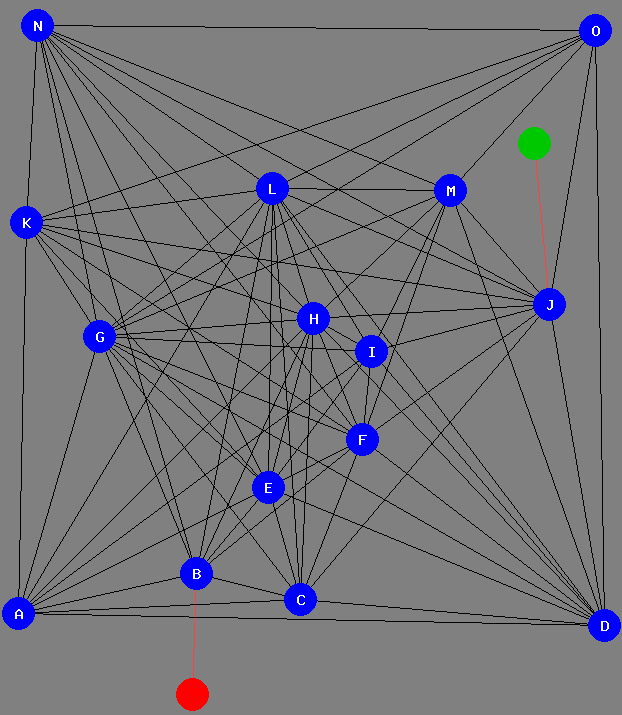 . Note that two of the connections are not usable, since they cross the connection from the Start to node
 B. Also note, that the Start and End can be approximated by circles too, as there are no connections that are going by too close to them to cause any trouble. For other node positions this might however by different!
Finding all connection crossings:
The same was done for the crossings of connection. I used a formula for line intersections for this. I used one which calculates "u" and "t" as the position of the crossing on the lines. This time we need to check, if the crossing is on both of the connections tested. Also if using the "u" and "t" checking for >= 0 and <= 1 also finds a collission if the two connections share one point! So either check for >= 0.001 and <= 0.999 or test if any node is used by both connections in test. When now adding the initial connections manually and showing all possible interconnections left we get: 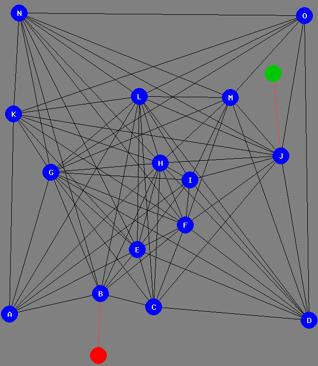
Optimizations on collissions:
As this is time consuming, I also precalculated a collission table. This holds all connections that would collide, if I use one special connecton. Instead of checking this list over and over again, I maintained a list of all possible connections that can still be made and a list of connections that were used so far. When progressing and choosing one of the usable connections, it is added to the list of used connections and removed from the available connection list. Also all colliding connections are removed by using the precalculated table. Hence, we can just pick one connection from the 'available' list. When going recursively backwards, this change to the lists must be restored...
Intermediate solutions when ignoring the rules on how the signal follows the connections:
The next step was to just visit every node, before reaching node "J". This time ignoring the rules how the signal would travel, but not allowing crossing connections. I used a list of nodes that must still be visited and initialized it with all nodes from A to O and started the search at "B", which automatically removed "B" from the "toVisit" list. Then from there it recursively tried all possible combinations, which surprisingly didn't take too long (~3 minutes) even I just used a very inefficient programming language (PHP) in terms of speed. I chose it because producing images with it is very simple. It only found 45255 solutions, which was also surpring me. The original Traveling Salesman Problem problem would have taken ages and find millions or billions of solutions. But it seems that not being allowed to cross any connection, that was traveled before, speeds up the process extremely and at the same time reduces the number of solutions.
Implementing signal path rules:
At first glance it seemed really challenging to implement this rule in a computer, since you would need to go through all connections that are used, calculate angles... in the right direction (always the direction pointing from the current node visited away), order them and then somehow estimate which is the first, second and so on. How could that be solved quickly? -- I already had the list of all possible interconnections. Hence, I could go through all nodes in advance and calculate the angle for each connection that leaves them. To calculate the angles the atan2(dy,dx) function is very helpful! Then all connections for each node are stored in a list, ordered by the angle. It doesn't matter which angle it starts. If we later want to estimate the path followed by the signal, we go through that list for the current node we are at and follow the order it is in! We create a new list storing any connections that are "used" so far, in the order we find them. Also we note down the list index of the connection we used to get to this current node as indexEntered, which will always be contained in this list... then as the list index starts by 0, we can simply calculate index = (indexEntered + signalStrength) % length(list) to get the exit node.
Simple approach:
Now we not only need to add the links we want to follow, but also some links that ensure the signal goes the way we want it to go. As it was so quick to find the 45255 solutions for all the pathes without crossing connections, but ignoring the signal strength rule, I used a simple approach: At each node I tried trough all the permutations of still allowed connections originated from that node. To do that, I estimated the number $n$ of connections from the 'available' list that are related to the current node. Then I cycled through the $2^n$ possiblities, knowing that this quickly becomes a high number but hoping that using lots of connections would also cause most of that possibilities would very quickly die out in the near progress having to many connections in the way to reach other nodes. It worked, but it's very slow. So far it found 269 solutions having searched less than 1% of the problem space. Looking at those solutions showed a further insight: 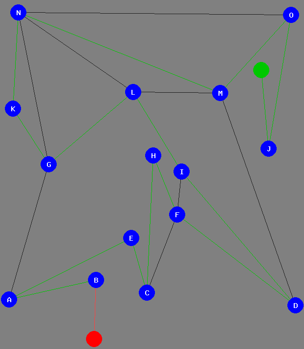
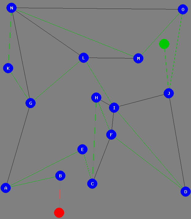 . Even if the path the signal takes stays the same, there can be multiple solutions!
Finding all solutions faster:
As cycling though all that permuations seems to bee too slow, it might be much faster to find those 45255 solutions for just visiting all nodes (ignoring how the signal would flow) first and then add additional connections to make the signal flow as we want. This is one of the strategies I used to find my solution by hand. However, there is another strategy we could use to speed things up: the rule about the number of connections that need to be there to not make the signal flow backwards; I decided to find/store the 45255 intermediate solutions which took 34 minutes. That was 10 times slower than last time, most probably because I also generated the compressed *.png files. However, I can now cycle through those intermediate solutions and try to resolve them. Also I can do statistics on how many of them finally had real solutions and so on.
Final Results:
As far as my program is correct, there are 34834 real solutions. My new program needed ~88 minutes to find them (and save results inkl. images) by using the intermediate solutions. Only 553 out of the 45255 intermediate solutions have at least one real solution. This means just finding a random path without crossings to the goal has only a ~1,22% chance of success. However, most pathes that have a solution have really many of them. Only 23 of the 553 have only one real solution. The intermediate solution with the most final solutions is depicted following image. It has 1806 solutions... just by varying the "unused connections". 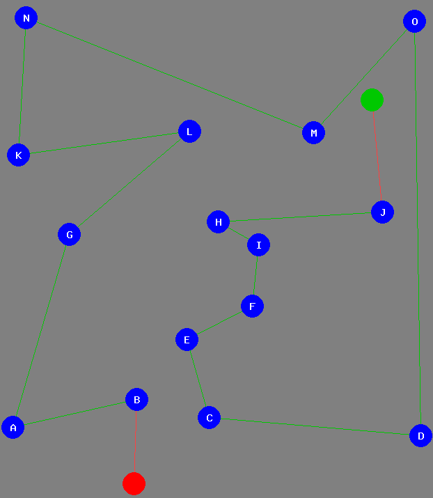 Note that I'm not supplying all solutions here, so you can solve the puzzle yourself and find any of the other over 34800 solutions that were not shown here so far!


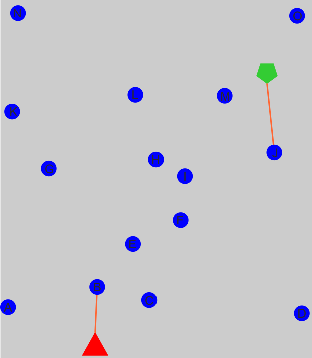


 . Note that two of the connections are not usable, since they cross the connection from the Start to node

 . Even if the path the signal takes stays the same, there can be multiple solutions!
 Note that I'm not supplying all solutions here, so you can solve the puzzle yourself and find any of the other over 34800 solutions that were not shown here so far!