8
$\begingroup$

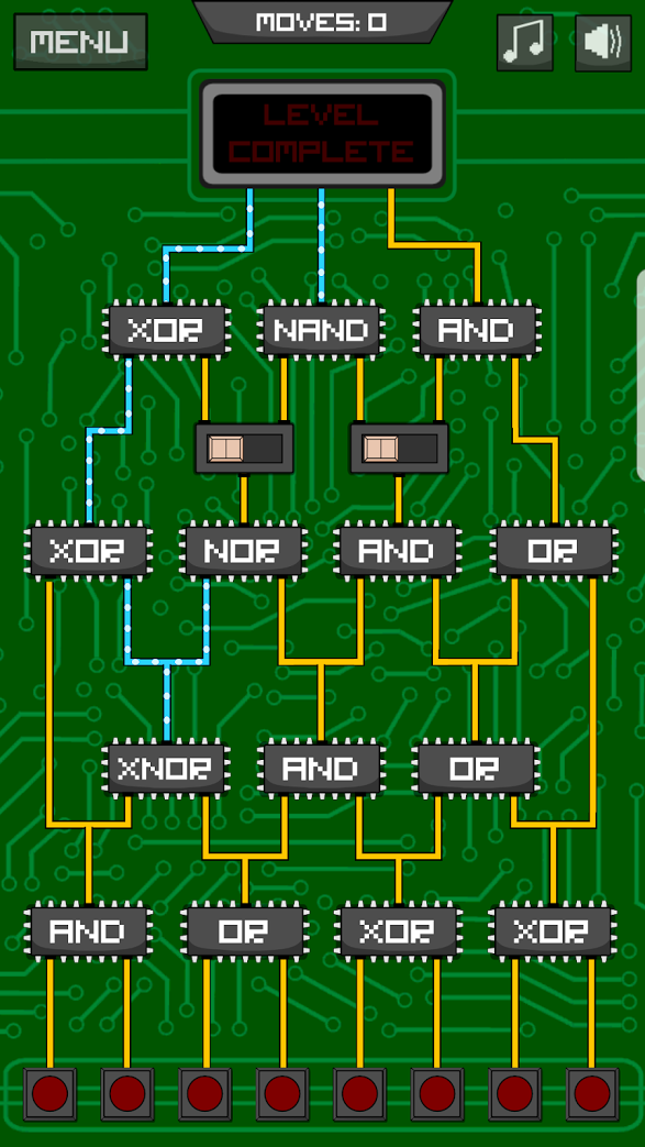
I have a game on my phone (Circuit Scramble on Android) which is a game in which you need to work out what set of inputs and switch positions will allow you to power the "level complete" sign.

I have found one puzzle from the randomly generated section which I cannot find a solution for:

Puzzle I am stuck on

The options you have to choose from are to toggle any of the inputs at the bottom and to move either of the switches in the middle of the puzzle.

To complete the level all of the inputs to the top must be ON.

I've also created a play version of this on a cool site I found: https://simulator.io/board/F0aztyxm5D/1 - I couldn't work out how to do switches so you'll need to just add wires in to match the position of your switch. Also the NAND, NOR and XNOR are simulated by a NOT gate following the appropriate gate.

My current logic is as follows (hidden in case anybody wants to puzzle over it themselves first - please note that I believe this puzzle has no solution):

The AND on the top row must have both of its inputs set which means that likewise the AND in the row below that and the one below that must all have their inputs (and outputs) set. If we then look at the NOR gate in the second row because the AND below it must be outputting then it must be getting an input which means it will never output anything. This in turn means that the XOR on the top left must be receiving an input from its left hand connection.

This means that the XOR on the second row must be receiving one and only one input. This means either the XNOR on the third row must be outputting or the AND on the bottom left must be outputting. THE XNOR in question is already getting an input on its right terminal (the OR needs to power the AND) which means the only way it can output is if the left terminal is also on. However the left terminal being on means that the XOR above is now getting input on both its terminals. It is however obvious that we can't power the left wire without also supplying to the XNOR which we've just established is wrong.

So that's my logic that suggests this is impossible.

So the question: Is there a valid solution to this puzzle such that all three wires at the top are powered?

Appendix 1 - Element Logic

AND - output ON only if both inputs are ON
OR - output ON if one or both of the inputs are ON
XOR - output ON if one and only one input is ON
NAND - output OFF only if both inputs are ON (same as AND but output reversed)
NOR - output OFF if one or both of the inputs are ON (same as OR but output reversed)
XNOR - output ON if both inputs are the same (ie both ON or both OFF) (same as XOR but output reversed)
SWITCH - the input is transmitted to the side the switch is on, the other output is always off. eg if switch is left and input is ON then left is ON and right is off. If the input is OFF both are OFF. Wires - In the image Wires are either yellow or blue and white. They are both the same. The difference is because the blue and white show ones that are currently ON in the visible configuration.

$\endgroup$
14
  • $\begingroup$ Not sure if there are any more relevant tags for this. It feels very untagged at the moment due to how broad the logical deduction tag seems to be... $\endgroup$
    – Chris
    Commented Jul 11, 2017 at 11:45
  • $\begingroup$ Does a switch send the signal below to whichever side above the switch position is, and an OFF to the other side? $\endgroup$
    – Gareth McCaughan
    Commented Jul 11, 2017 at 12:01
  • 1
    $\begingroup$ Wow, I just downloaded and played this yesterday. I do agree with your conclusion that this puzzle is not solvable. $\endgroup$
    – Rob Watts
    Commented Jul 11, 2017 at 20:03
  • 1
    $\begingroup$ Although a race condition suggested by Kruga would not be the intended puzzle interpretation, it might explain how the automatic generation of the puzzle failed to generate a valid puzzle, because if the generator randomly set the gates and then randomly switched on some inputs and toggled some switches, and the propagation was not instantaneous, then the outputs may at some point be all true. Side note: This phenomenon can actually happen in real circuits, so it is something to beware of. $\endgroup$
    – user21820
    Commented Nov 8, 2021 at 9:08
  • 1
    $\begingroup$ @Chris: For example, set the switches as in Peter Taylor's answer and then turn on input 5 then input 3 then input 2 then input 1. Just before the last input change, outputs 2,3 both are on and the XNOR output is off, so if the last input change is propagated one gate at a time output 1 will turn on before output 2 turns off! $\endgroup$
    – user21820
    Commented Nov 8, 2021 at 9:13

2 Answers 2

5
$\begingroup$

I also think this is unsolvable. My reasoning resembles Chris's:

  1. Top-right AND must have both inputs 1.
  2. Right-hand switch must be positioned right, and input to that switch must be 1.
  3. Output of AND gate below that switch must be 1, so both its inputs must be 1.
  4. Output of AND gate below that must be 1, so both its inputs must be 1.
  5. Right-hand input of XNOR gate near bottom left is 1, so left-hand input and output must be equal.
  6. The two inputs to the XOR at middle left are equal, so output is 0.
  7. Top-left XOR's left input is 0, so its right input must be 1.
  8. Output of middle-left NOR must be 1, so its inputs must both be 0.
  9. Now we have a contradiction, because 3 says left input of middle-right AND is 1 but 8 says right input of middle-left NOR is 0, but those two are tied together.

I've also brute-forced it by computer; of course my code may have bugs but probably not the same bugs as my reasoning above. This displays intermediate results as well as final output.

for n in range(1<<6):
    s = (n>>4)&1, (n>>5)&1
    r = n&1, (n>>1)&1, (n>>2)&1, (n>>3)&1 # just above bottom gates
    t = [r]
    r = r[0], 1-(r[0]^r[1]), r[1]&r[2], r[2]|r[3], r[3]
    t.append(r)
    r = r[0]^r[1], 1-(r[1]|r[2]), r[2]&r[3], r[3]|r[4]
    t.append(r)
    r = r[0], (1-s[0])&r[1], s[0]&r[1], (1-s[1])&r[2],s[1]&r[2], r[3]
    t.append(r)
    r = r[0]^r[1], 1-(r[2]&r[3]), r[4]&r[5]
    t.append(r)
    win = r[0]&r[1]&r[2]
    print("%.02d"%n,t,win)

Notice that no line of its output ends in a 1.

$\endgroup$
1
  • $\begingroup$ Thanks for taking the time to look. I'll not accept the answer immediately just in case something else comes along. Hopefully I won't forget to come back here and accept later. :) $\endgroup$
    – Chris
    Commented Jul 11, 2017 at 12:15
9
$\begingroup$

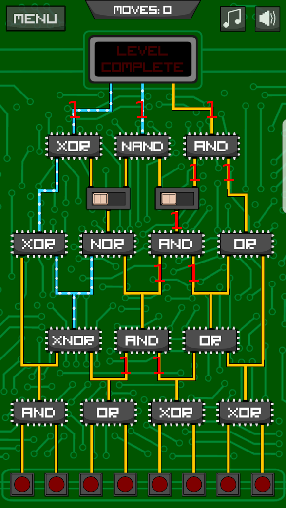
It's easier to see what's going on with a diagram. Working down from the top, we can see the following:

Set some 1s working backwards

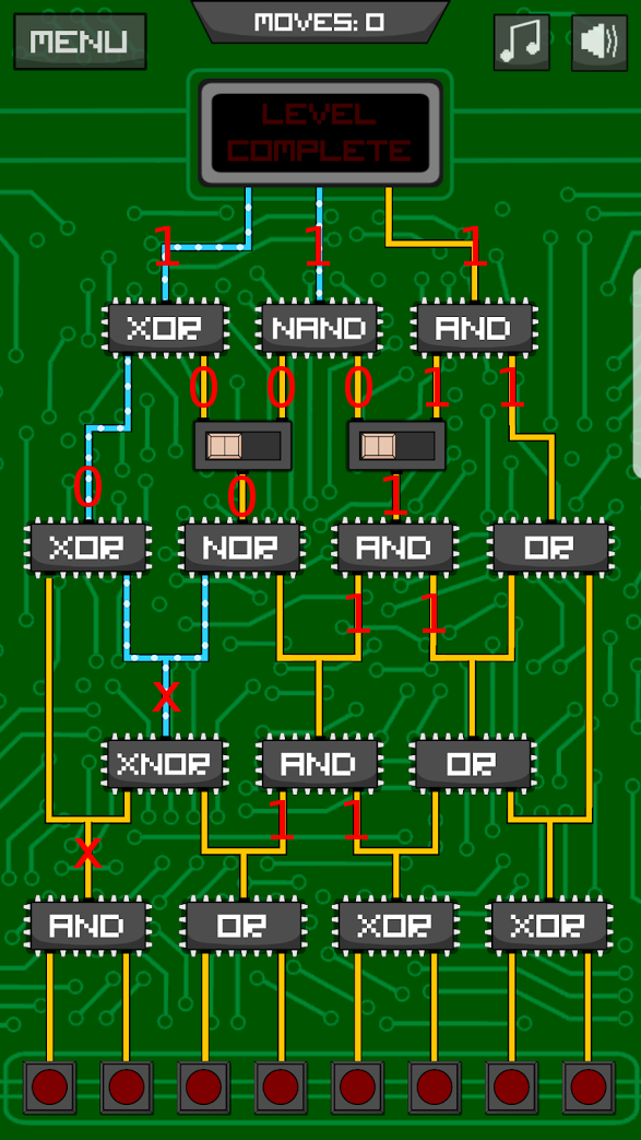
Then working up from the bottom (ignoring the right hand side, which is easy but irrelevant), we can see the following:

Set some 0s working forwards

And we have a contradiction in the top-left XOR.

$\endgroup$

Your Answer

By clicking “Post Your Answer”, you agree to our terms of service and acknowledge you have read our privacy policy.

Not the answer you're looking for? Browse other questions tagged or ask your own question.